THE TREE
Project Process
July 2023
Introduction: The aim of this project is to explore how emerging technologies can provide new cost-effective approaches for design and fabrication, and discover materials with relatively low embodied carbon that are compatible with such approaches. Specifically, the project focuses on free open-source tools for two reasons: 1. they are more accessible than commercial tools because they have no cost barriers and are modifiable; 2. the pool of open-source tools is diverse and resourceful. The use of all open-source tools in this project complies with corresponding licensure agreements. Two prototypes are expected to be developed at the end of the project: 1. a physical prototype that is produced with mentioned approaches and materials, 2. a process prototype that is integrated from design to fabrication and contains within itself a feedback loop for incremental improvements.
1. Script-Based Form Generation
Structures in nature are an aesthetic and functional inspiration for the design concept. Specifically, fibers in tree bodies form structures in response to genetic prescriptions, external forces such as gravity and wind, and the need for water and nutrition transportation, the resulted geometries are often found beautiful. In early project design, an attempt was made with computer code to translate such mechanisms from nature into digital simulation. The basic form was constructed using modified Sverchok scripts in Blender based on particle travel paths in a vector field, which was formed by mostly written mathematical rules and a small amount of randomness. Since a full molecule-based, gravity-driven simulation is extremely difficult and requires large computational capacity, lines directing growth directions were put in place manually.
A fabrication strategy was developed in this early phase: the model is broken down into smaller pieces that can fit into common desktop 3D printers, the pieces are held together with wood glue and wood dowels, the long cantilevered branches are supported by embedded metal rods. Additional strings might be needed to structurally support the metal rods.

Growth Vectors

Modular Attachment Units

Assembly Parts

Assembly Parts

Rendering
2. Script-Sketch Hybrid Form Generation
Sculpting and hand sketching are among the most ancient ways of human expression. Built on the idea of vector fields from the script-based approach, a tool that combines scripts and sketches was developed, named Vectorio. The tool was first tested in 2D with Pygame, after a successful proof of concept, it was turned into 3D space and iterated with Ursuna and GLFW.
In the 3D environment, particles travel along paths guided by a vector field generated from scripts and sketches. In several tests, particles also interact with each other. Particles generate densities in a density grid when traveling, which are later translated into point clouds that are used to generate solid mesh forms.

2D Particle Proof of Concept

2D Sketch Proof of Concept
Although it was not realistic to run detailed simulations, directionality and tolerance were seen as critical in translating structural and assembly viability into geometry. Vectors were programmed in a way that avoided sharp turns and low tolerance.

Directionality and Tolerance

3D Particle Test

Density Grid

3D Path Test

Pre-Mesh Point Cloud

Form Generation Demo

Rendering
3. Structural Evaluation Through FEA
Model of The Tree was imported into FreeCAD and PrePomax where static-state structural analysis was performed through FEA (finite element analysis). Despite geometric simplification, the complexity of the model quickly reached the capacity limitation of the tools, instead of performing full simulations and iterations as originally planned, the team performed preliminary analysis aiming to find weak spots in the model and made adjustments to the model based on the analysis results.
Further development of a structural analysis approach integrated with smooth feedback and structural optimization is desired.

Gravity Only FEA Visualization

Gravity and Fixed Surface FEA Visualization
4. Fabrication
Redesigning a fabrication strategy, the team identified two categories of focus: parts and joints. By geometric modification, joint design and weight distribution through assigning different infill densities, the team eliminated supporting metal rods that were included in the early conception.

Process Concept

Slicing Concept
Common products of 3D printing materials are usually made of plastic polymers, or plastic with a small portion of non-plastic ingredients. Some categories of these plastic polymers are biodegradable under certain conditions. Others have tried to use completely bio-based materials to 3D print large structures, such as coffee beans. Such materials are technically possible to be used for The Tree but require processing of raw materials and appropriate hardware.
The team chose wood-fused PLA filaments as the main material for the parts. The selected type of filament contains 85% of PLA and 15% of wood particles, which is expected to have similar plasticity and strength properties as plastic and additional features brought by the fused ingredients.

Pre-Cleaning Wood PLA Print with Support
Post-Cleaning Wood PLA Print with Support
Joints were designed to act similarly to expansion anchors. Correspondingly, grooves were made in holes that receive joints to increase friction. One of the desktop 3D printers does not work well with composite materials such as wood-fused PLA, the team mitigated defects in prints by modifying GCode that drives the printing process.


Grooves in Joint Receiving Hole
3D Printed Custom-Designed Joints


Material Flow Difference
Resumed Prints Patched with GCode Modification
Print with Color Fusion

Parts were printed in three different colors.


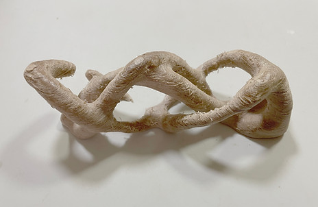
Printed Parts

The Tree - Physical Prototype
5. Conclusion
Due to the use of free open-source tools and desktop 3D printers with GCode modification, the project cost less than half of that originally projected using commercial tools and services. Because a significant amount of time was spent on developing and learning tools, and there was no shipping or queuing time for the printed parts, it is difficult to compare spent time with a process that uses commercial services.
Several areas of future opportunities have been identified:
a. Form generation, such as software that makes form from sketches, and form design in VR (virtual reality).
b. Structural analysis and optimization, such as performance-based structural analysis through simulation, and evolutionary algorithms for structural optimization.
c. Additive manufacturing, such as self-supporting large-scale 3D printers and assemblers.
d. Binder materials, such as bio-based resin or materials that can integrate waste industrial materials into usable construction materials.
e. Standardization, such as criteria that can be used to identify, test and evaluate additive manufacturing materials.